Follow the below mentioned steps for a preliminary guideline. Pipe racks are structures in petrochemical chemical and power plants that are designed to support pipes power cables and instrument cable traysThe design requirements found in the US building codes are not clear on how they have to be applied to pipe racksThis course summarizes the US design code.
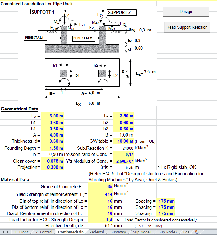
Combined Foundation For Pipe Rack Spreadsheet
Live Load shall be applied on platform in the top level of rack as servicing cooling tower access.
. Magnitude and direction of loads being transmitted to the. Their main function is to offer support to power cables instrument cable trays and pipes in general. Now check the next nearest thickness available in the ASME B3610M considering the required thickness tm.
Pipe rack is the main artery of any oil gas or refinery plants. Pipe rack design is one of the significant aspects of plant design and a good design contrbutes to integrity and reliability of the plant and the associated structures. UDL Piping loads Empty Operation Transverse TOC EL 104500 15 kNm 30 kNm TOS EL 107500 15 kNm 30 kNm TOS EL 110500 15 kNm 30 kNm Longitudinal TOC EL 103250 075 kNm 15 kNm TOS EL 105750 075 kNm 15 kNm TOC EL 108250 075 kNm 15 kNm TOC EL 111500 075 kNm 15 kNm Anchorage Loads 5 Operation Pipe Load TOC EL.
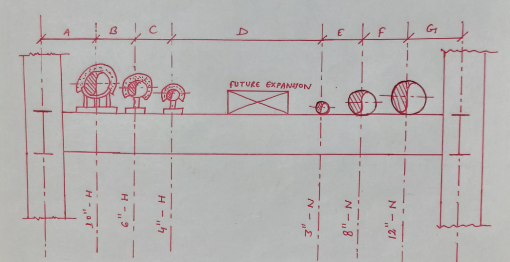
Select an elevation of pipe rack and check what are the lines running over that rack. Ad Choose from 25M Verified Suppliers. A transposition drawing takes the.
The tributary area is the tributary height times the tributary length of the cable tray. It can give you a real feel for what you want to try to do with the real pipe. The book is appropriate primarily for pipe design in the petrochemical industry.
Concrete Piles f c 4000 psi f y 60000 psi Diameter 25 ft Clear Cover 3 in. Application of wind load for pipe racks. Calculating loads on the pipe racksyour trainer proceeds step by step through the process of modelling columns beams stringers bracingapplying dead loads product loads thermal loads wind loadsnext he proceeds further on how to assign the properties to the structural steel members assigning.
This method requires the. The 500 mm differential between pipe runs is the absolute minimum. The growth of such utility headers should be determined by multiplying the coefficient of expansion by the length of the line.
The width of the pipe rack is estimated as per below equation W f x n x s A B f Safety factor 15 if pipes are counted from the PFD 12 if pipes are counted from P ID. 07 on pipes. Length 33 ft Pile embedment 6 in.
Calculate transverse wind on each cable tray level. ATransverse Beams In computing the allowable bending stress Fb the unbraced length shall be taken as the span of the beam and the AISC factor Cb shall be used to account for end fixity. Design Calculation Report - Pipe Rack - And Foundation eljq1w5q0541.
Foundation Loads Load Case Load kips P 1 P 2 P 3 P 4. Design Data Concrete Piers Size 15 ft x 15 ft Pile Cap Foundations f c 3000 psi f y 60000 psi Thickness 3 ft Clear Cover 2 in. In the absence of defined piping loads and locations an assumed minimum uniform pipe load of 20 kPa should be used for preliminary design of pipe racks.
Check the allowed maximum movement outside loop say 75mm and place the first anchor at a distance which will be nearer to the allowed thermal movement 75mm as mentioned above. Select the line with maximum temperature first. The tributary height for each pipe level should be taken as the largest tray height plus 10 of the pipe rack trans- verse width.
Sign in to download full-size image Figure 10-2. Add 20 future. The maximum segment for the pipe rack shall be limited to 42 m in length unless calculations indicate otherwise.
There are several ways to determine the width of a pipe rack. T m t c 1250 mill tolerance for seamless pipe is 125 t c 0875 9380875 tm 1072 mm This is the minimum pipe thickness required to withstands for the given design pressure and temperature. Design Graphics and Engineering Technology through the creation of piping arrangement and isometric drawings using symbols for fittings flanges valves and mechanical equipment.
N Number of lines in the densest area upto the size of 18 Inch s 300mm estimated average spacing 225mm if lines are smaller than 10 Inch. Ad Choose from 25M Verified Suppliers. A process unit or carries the pipe and cable trays from one unit to another.
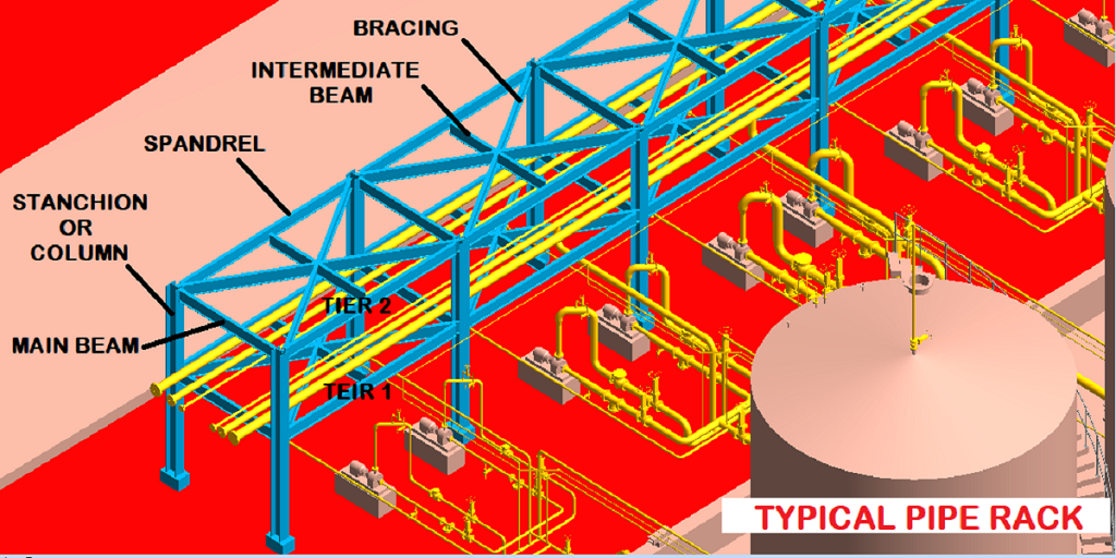
Use a mini- mum force coeffi cient of C f. Pipe rack can be considered as the main artery of a plant piping system. In this case the E-W pipe rack height will be 12 from grade and the N-S pipe rack height will be 15 from grade.
Make a close-to-scale model of your pipe configuration using that piece of copper wire. Live Load in operating or maintenance platform are 250 kNm2 Live Load 25 x 3 75 kNm --- span 3 m Page 7 of 15 f CALCULATION OF PIPE RACK STRUCTURE Doc. The steel pipe rack design play an important role in the proper functioning of the power plants.
The future space age is normally based on the client requirements. The aforementioned industry standards and specifications apply because they are referenced by the IBC. Push the ends together to see where the deflection goes and what bends the most.
Width of Pipe rack The width of the rack shall be 6m 8m or 10m for single bay and 12m 16m or 20m for double bay having 4 tiers maximum. More than 350 illustrations and photographs provide examples and visual instructions. In the case of pipe racks additional design criteria are provided by Process Industry Practices PIPSTC01015 PIP 2007 and ASCE guidelines for petrochemical facilities ASCE 1997a 1997b.
Holds up to 32 Diameter Reels - 300 lb Load Tested - more. You will start with the absolute basics ie. Typical pipe rank intersection.
Generally lines running at right angles to main pipe rack are assigned elevations 500 mm1 m higher or lower depending on headroom requirements than lines running in main pipe rack. The spacing between pipe rack portals shall be taken as 6m in general. Bend it into the shape of your pipe configuration and set it down on the desk.
The pipes and cable trays from one equipment to another equipment within. Pipe rack construction material Steel Cast-in-situ concrete Pre-cast concrete shall be as per project design criteria. This corresponds to an equivalent load of 6 in 150.
6 rows Calculated pipe rack width 650585410325260475590 3295 mm. Contact Directly Get Live Quotes. Contact Directly Get Live Quotes.
This is usually done during the plot plan development by creating a piping transposition drawing from PIDs and a preliminary equipment layout. Select an elevation of pipe rack and check what are the lines running over that rack. The most appropriate application would be to assume the pipe rack is an open structure and design the structure assuming a design philosophy similar to that of a trussed tower.
Piping Gravity load D. Sometimes the pipe racks can also be used for offering support to mechanical equipments and vessels apart from valve access platforms. See Table 3-1 below for Cf force coefficient.
The PIP practices and ASCE guidelines may be used.
Pipe Rack Design And Calculations Make Piping Easy

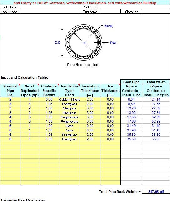
Calculation Of Pipe Rack Weight Spreadsheet

Design Of Pipe Rack Layout Considerations

Design Of Pipe Rack Layout Considerations
Calculation Of Pipe Rack Weight Spreadsheet
Pipe Rack Design And Calculations Make Piping Easy

Pile Capacity All Calculations Spreadsheet Nursing Student Tips Spreadsheet Design Spreadsheet

Design Of Pipe Rack Layout Considerations
0 comments
Post a Comment